Installation Issues
1. When attempting to reinstall software, if the old version is already running, please close the software before attempting installation again.
2. ToupLite software does not support Windows XP and Windows Vista systems. When attempting to install ToupLite, please use Windows 7 or higher. ToupView software supports XP (32-bit) and Windows Vista, 7, 8, 10 (32-bit and 64-bit).
The common cause is that the old DirectShow driver is being used by third-party software. Please close any software that might be using the DirectShow driver and try again.
It is best to use SHA1 digital signature as it supports Windows XP / Vista / 7 / 8 / 10. If SHA1 is not available, SHA2 can also be used. However, SP1 patch must be installed on Windows 7.
Driverless installation does not mean no driver is needed. It means the camera will use Windows built-in drivers. UVC cameras can use UVC drivers from all Windows platforms. For regular USB 2.0 and USB 3.0 cameras that do not support UVC protocol, they can support WinUSB drivers on Windows 8 and Windows 10.
When attempting silent installation, please use the /S option. Or use the provided .bat file for one-click silent installation.
Sensor Related
It is actually difficult to describe which one is better. CCD and CMOS are two different sensor types using different technologies. CMOS can be considered mostly digital sensors, while CCD are mostly analog sensors, with different drive circuit systems. Traditionally, CCD was viewed as high-end products and CMOS as low-end products (except sCMOS). But now the situation is completely different. With CMOS technology development, CMOS can achieve performance equal to or better than CCD. Sony has announced discontinuation of CCD products and replacement with CMOS because they have strong confidence in the new generation CMOS. CMOS has now become better in several aspects: sensitivity, noise control, and output speed. It is certain that CMOS will be the future.
For rolling shutter sensors, each row of pixels is exposed at different times. For fast-moving objects, images obtained from rolling shutter sensors will have some degree of distortion. Global shutter sensors can solve this problem because every pixel in the sensor is exposed simultaneously. Due to the complex architecture of global shutter sensors, global shutter sensor cameras are more expensive than rolling shutter ones, and readout noise is also slightly higher than rolling shutter sensors.
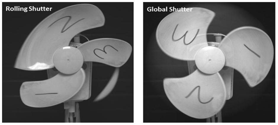
Left: rolling shutter, Right: global shutter
USB Connection
When the camera is plugged into the computer via USB, the first step is that the camera will first be recognized by Windows, and the second step is to load the corresponding driver.

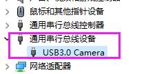
If everything is normal, you can find the camera in the 'Cameras' list in Device Manager. For Windows 8 or higher, when using WinUSB driver, it will appear in the 'Universal Serial Bus devices' list in Device Manager.
After installing the software, plug in the camera. If you cannot find it in the 'Cameras' list or 'Universal Serial Bus devices' list in Device Manager, try to find it in the 'Other devices' list with the name 'USB 2.0 Camera' or 'USB 3.0 Camera'.
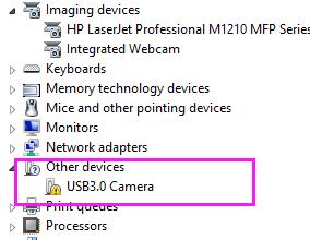
If it is in the 'Other devices' list, right-click on the device, then find the update driver button in the pop-up menu. Select the driver in the installation directory and complete the update process. The driver can be obtained from the SDK directory toupcamsdk.202XXXXX\win\drivers.
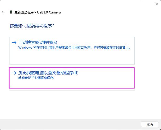
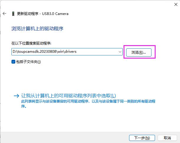
If the camera cannot be found in the locations mentioned above, it means Windows cannot recognize the camera. Please check the USB connection and try reconnecting the USB connector again. If reconnecting has no effect, try changing to another USB port on the computer, or try replacing another USB cable.
If you are sure the camera is not in Device Manager and the USB connection is good, it means the camera has failed or there is a problem with the USB connector on the camera.
Ensure the USB 3.0 camera is plugged into a USB 3.0 port. This can be verified by checking the connection status in Device Manager.
If it is confirmed that the camera is connected to a USB 3.0 port, the most likely cause is a USB connection problem. Please reconnect the USB cable. When inserting into the USB port, the insertion process should be as fast as possible. A slow insertion process is one of the reasons why USB 3.0 is recognized as a USB 2.0 device. Alternatively, you can connect the USB data cable to the camera first, then connect it to the computer, which can better avoid being recognized as USB 2.0. If this does not help, please try replacing the USB 3.0 cable. Additionally, computer motherboards using non-standard third-party USB controllers or non-standard external PCIe-to-USB 3.0 adapter cards may also cause this problem.
Step 1: Ensure you are using the latest software. Especially for USB 3.0 3.1 MP, 5 MP, 8.5 MP, 10 MP cameras. For the above models, new cameras using old software may cause this problem.
Step 2: Please check USB connection first, especially USB 3.0 cameras. Replacing USB cable is a good attempt to determine if it is a connection problem.
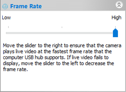
Step 3: If the above steps do not help, please set a lower frame rate level in the software sidebar.
Step 4: If the above steps do not help, there are two possible reasons. One reason is camera failure. The second reason is that the USB controller transfer performance may not be good enough. For USB 2.0 cameras, the UA series with buffer will solve this problem. For USB 3.0 cameras, we recommend using Intel USB 3.0 host controller instead of third-party ones. For third-party chipsets, performance cannot be guaranteed. If using external PCIe-to-USB 3.0 cards, performance cannot be guaranteed. Please choose standard PCIe expansion cards.
For USB cameras, please confirm whether the camera is displayed in Device Manager and whether the driver is installed. Please refer to the question 'Insufficient USB bandwidth'.
For Wi-Fi cameras, please confirm whether the camera and computer (or mobile device) are connected to the same network.
For USB cameras, if it is displayed in Device Manager and the driver is installed correctly, the most likely reason why the camera is not displayed in the software is that the software version is incorrect. Please update the software.
For Wi-Fi cameras, if the camera and computer (or mobile device) are connected to the same network, please try updating the software and check again.
When 12-bit cameras work in 12-bit mode, the video obtained from the camera has more information and is more accurate. If further color processing is needed, the calculation process will be more accurate, and fewer artifacts will be seen in 12-bit mode (such as gamma or contrast enhancement).
For monochrome cameras in 12-bit mode, especially when users use it for measurement, 12-bit video or images are more accurate for their further calculations.
For USB 3.0 cameras, starting from firmware version 1.5.0, the firmware inside the camera can be updated through the USB interface and a dedicated tool is provided. When you want to update firmware, if your version is after 1.5.0, please contact sales representative.
1. Uninstall the original proprietary protocol (if multiple versions exist, uninstall multiple times to completely remove the original proprietary protocol until the camera cannot be recognized in Device Manager and shows yellow exclamation mark)
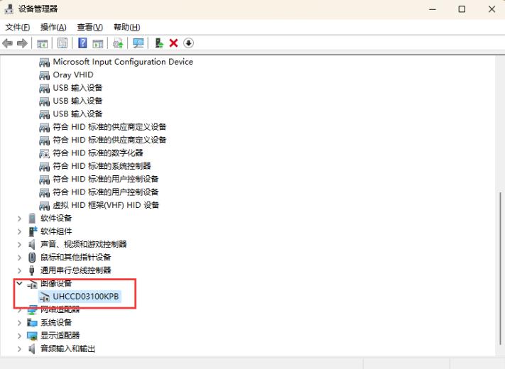
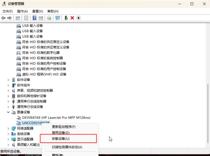
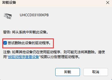
2. Find the unrecognized camera in Device Manager
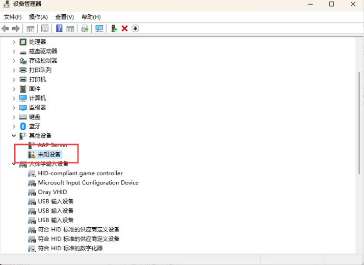
3. Right-click to update driver
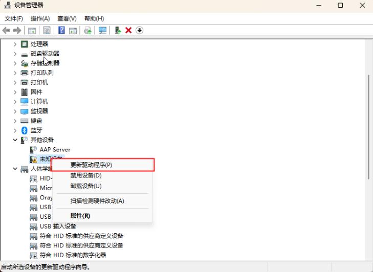
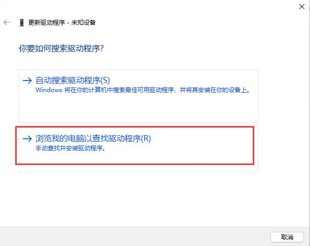
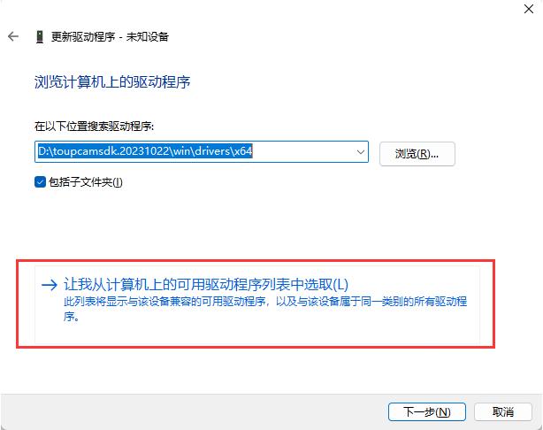
4. Select Universal Serial Bus devices
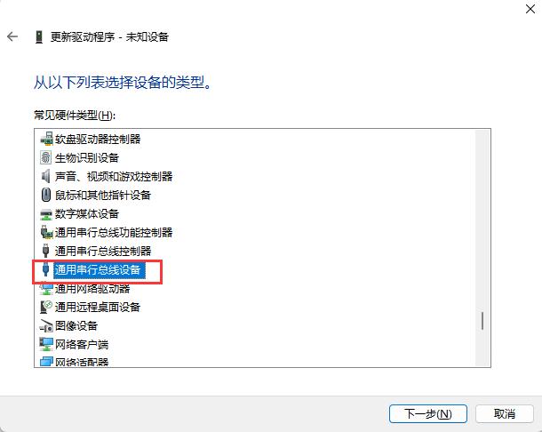
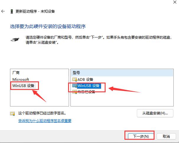
5. Click 'Yes' when warning appears, forcing use of WinUSB driver
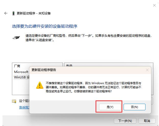
6. Finally the camera is recognized as WinUSB device in Device Manager
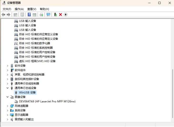
Note: If you plug in a new camera that supports WinUSB or use the old ToupCam driver, the above method may fail.
When the camera is plugged into the computer via USB, the first step is that the camera will first be recognized by Windows, and the second step is to load the corresponding driver.

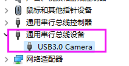
If everything is normal, you can find the camera in the 'Cameras' list in Device Manager. For Windows 8 or higher, when using WinUSB driver, it will appear in the 'Universal Serial Bus devices' list in Device Manager.
After installing the software, plug in the camera. If you cannot find it in the 'Cameras' list or 'Universal Serial Bus devices' list in Device Manager, try to find it in the 'Other devices' list with the name 'USB 2.0 Camera' or 'USB 3.0 Camera'.
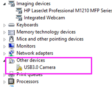
If it is in the 'Other devices' list, right-click on the device, then find the update driver button in the pop-up menu. Select the driver in the installation directory and complete the update process. The driver can be obtained from the SDK directory toupcamsdk.202XXXXX\win\drivers.
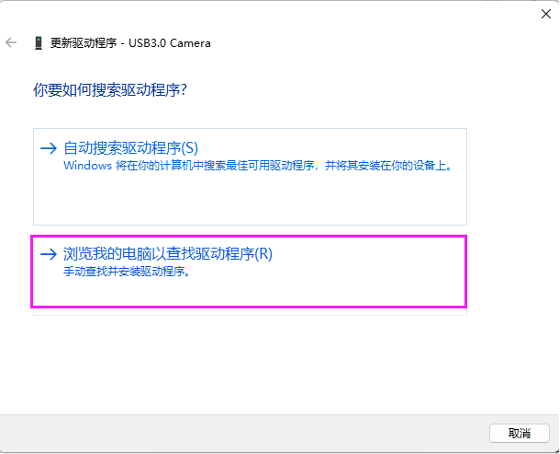
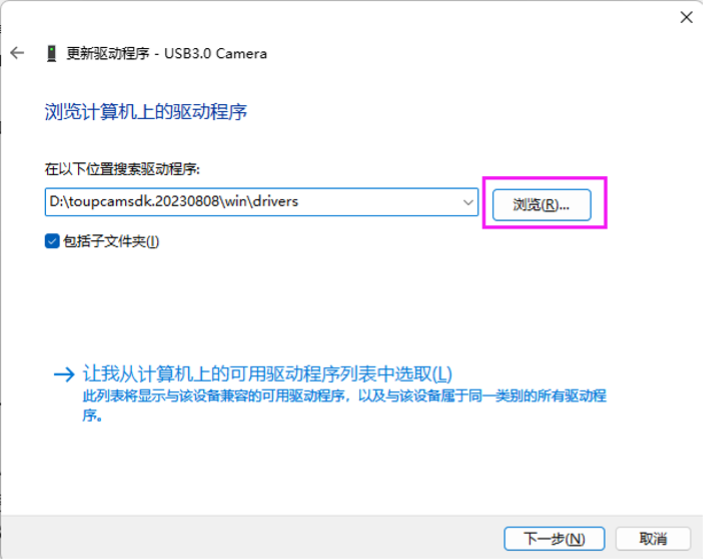
If the camera cannot be found in the locations mentioned above, it means Windows cannot recognize the camera. Please check the USB connection and try reconnecting the USB connector again. If reconnecting has no effect, try changing to another USB port on the computer, or try replacing another USB cable.
If you are sure the camera is not in Device Manager and the USB connection is good, it means the camera has failed or there is a problem with the USB connector on the camera.
The frame rate specified in the catalog is the fastest rate achievable. The following reasons may cause the actual frame rate to be lower than the frame rate marked in the catalog.
1) Exposure time too long. Frame rate is determined by two factors: output speed and exposure time. Exposure time determines how fast the sensor generates an image. Output speed determines how fast the image is transmitted to the computer. If exposure time is A (in milliseconds), the frame rate will be the slower of the frame rate marked in the catalog and the frame rate calculated through exposure time (1000/A). If exposure time is the reason why the frame rate is not as fast as expected, the exposure time can be reduced to achieve faster frame rate. If brightness is insufficient, gain settings can be adjusted.
2) Incorrect bit depth setting. For cameras with bit depth settings higher than 8-bit, selecting bit depth greater than 8-bit may cause slower frame rate. The frame rate marked in the catalog is based on frame rate in 8-bit mode.

3) If exposure time and bit depth are not the reasons, please check frame rate level settings and ensure they are in the correct position. Even though the rightmost is the fastest, if this is a performance issue, dragging it to the left may improve frame rate.
UA series cameras are buffer-enhanced versions of U series cameras. To improve USB connection and make transmission more stable, larger buffer areas have been added to UA series cameras. In this way, UA series can achieve higher frame rates than U series cameras and can be compatible with computers with poor USB performance.
For monochrome cameras, E3CMOS version is available, while E3ISPM version is not available. The reason is that monochrome cameras do not need complex ISP processes.
For color cameras, both E3CMOS and E3ISPM versions are available. E3ISPM cameras have much faster frame rates than E3CMOS cameras because there is a hardware ISP module on the camera to accelerate ISP processing. E3CMOS cameras use software ISP running on PC, which cannot run as fast as hardware ISP. E3ISPM cameras have the same image quality as E3CMOS cameras.
For USB cameras, please confirm whether the camera is displayed in Device Manager and whether the driver is installed. Please refer to question 3.
For Wi-Fi cameras, please confirm whether the camera and computer (or mobile device) are connected to the same network.
For USB cameras, if it is displayed in Device Manager and the driver is installed correctly, the most likely reason why the camera is not displayed in the software is that the software version is incorrect. Please update the software.
For Wi-Fi cameras, if the camera and computer (or mobile device) are connected to the same network, please try updating the software and check again.
For fluorescence applications, high-sensitivity sensor cameras are needed. If exposure time is only a few seconds, non-cooled cameras are sufficient. E3ISPM and E3CMOS cameras are very suitable. Users can select different models based on their sensitivity parameters. However, if the signal is very weak and requires long exposure, such as 3-5 seconds or more, cooled cameras are needed. When cooled cameras are set to low temperature (usually 0 degrees to 5 degrees is sufficient), during long exposure, dark current and temperature-induced noise will remain at very low levels, and images obtained from the camera can be very clean.
HDMI Cameras
HDMI autofocus cameras can support mouse control and measurement functions. They also have Wi-Fi connections for video output. Some autofocus cameras can also output UVC. During the autofocus process, the video is very smooth, and video can be saved to SD card without problems.
Specially designed mechanical devices and carefully selected motors ensure smooth and quiet focusing processes.
Please ensure the power adapter is connected and turn on the power button of the HDMI camera. The power LED of the HDMI camera will show blue when turned on.
If the monitor shows black screen, please check the following aspects:
- 1) Check if the cover of the HDMI camera has been removed.
- 2) Check if the light from the object to the HDMI camera sensor is clear. To confirm this, remove the camera from the microscope or other device to check if you can see ambient light.
- 3) Check HDMI connection. Reinsert HDMI cable or replace HDMI cable for confirmation.
- 4) Now the video format of HDMI cameras is 16:9, select the corresponding mode on the monitor.
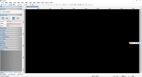
- 5) When UVC output is used, similar to the image below where there is device but no image or frames, it may be that antivirus software is turned on and restricted, it is best to turn off antivirus software.
Please contact sales representative to obtain upgrade files.
For XCAM series cameras, please refer to the following steps:
- 1. Extract the .rar file and copy the 3 or 4 files to the SD card. Do not put any other files in the SD card.
- 2. Put the SD card into the SD card slot on the camera.
- 3. Connect the camera to the power adapter and turn on the power button. The camera will automatically detect the upgrade files in the SD card and upgrade automatically. When the camera is upgrading, the blue LED will flash.
- 4. After a few minutes, the blue LED will stop flashing and remain solid, which means the upgrade is complete.
- 5. Remove the SD card with upgrade files from the camera to avoid automatic upgrade on next restart.
- 6. Restart the camera.
For ALPHA series cameras, please refer to the following steps:
- 1. Copy files to the SD card. Do not extract the .tar.gz file.
- 2. Put the SD card into the SD card slot on the camera.
- 3. Connect the camera to the power adapter and turn on the power button.
- 4. After the camera starts, find the 'About' button and click it with the mouse:

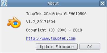
- 5. Select the target to update and wait for completion.
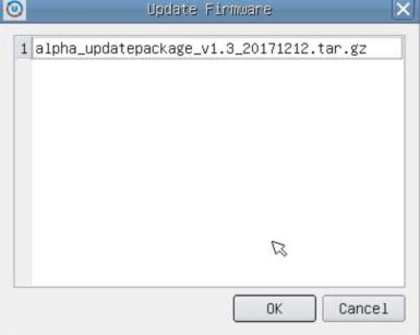
- 6. For OEM versions without 'About' button, click
 button to upgrade.
 - 7. After upgrade, please restart the camera.
For XCAM4K series, USB 3.0 video output function is implemented by UVC protocol based on ISO transfer. However, Windows 7 or lower versions do not support USB 3.0 UVC output. It can work on Windows 8 and Windows 10. To use USB video output function on Windows 7 or lower versions, users can use USB 2.0 cable or connect USB 3.0 cable to USB 2.0 port on computer. Video output is in MJPEG format, and video output frame rates are the same for USB 3.0 and USB 2.0.
How to diagnose XCAM4K camera if connected via USB and network interfaces but no video output?
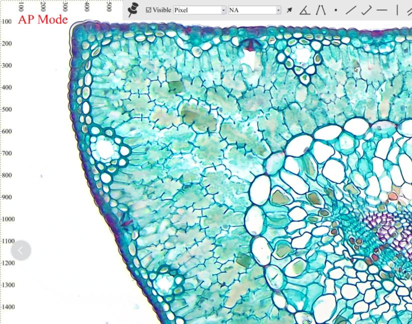
(Wi-Fi connection AP mode)
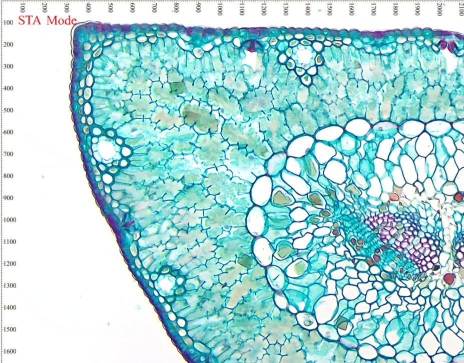
(Wi-Fi connection STA mode)
(USB connection)
(GE connection)
For network cameras, if computer can recognize camera network but ToupView software cannot recognize device, reasons are as follows:
- 1. Check if antivirus software has restricted ToupView software.
- 2. It may also be that computer's wired network segment conflicts with wireless network segment, recommend disabling computer's Ethernet first.
- 3. Try with another computer.
Any Wi-Fi adapter using the following chips can work with our HDMI and Wi-Fi cameras.
Realtek 8188eus, Realtek 8192cu these two are only compatible with PHB PHD series.
Starting from XCAM4K, cameras that support Wi-Fi need to use Realtek 8812bu.
Please refer to the following specifications.
|
Camera Model |
SD Card Format/Maximum SD Card Capacity |
Single File Size |
|
XCAM1080PHA |
FAT32 / 32G |
≤4GB |
|
XCAM1080PHB XCAM1080PHD XFCAM1080PHD |
FAT32 / 32G |
≤4GB |
|
NTFS / 128G verified |
≤2TB |
|
|
XCAM0720PHB XCAM0720PHC |
Video recording function not available |
|
|
ALPHA1080A ALPHA1080B |
FAT32 / 32G |
≤4GB |
|
EXFAT / 128G verified |
≤16EB |
|
Download Usage
System magnification is the product of optical magnification and electronic magnification. For microscope systems with cameras, if the objective magnification is A and the reducing lens magnification is B (eyepiece reducing lens or TV adapter reducing lens), the optical magnification is A×B. Electronic magnification is the display pixel size divided by the sensor pixel size (if the video is displayed at 100% zoom ratio).
Images with calibration information captured by older software may experience this issue. Using the new software will resolve the problem.
For cameras supporting beyond 8-bit, first set the camera bit depth to beyond 8-bit (12-bit or 14-bit) to capture files beyond 8-bit. Select the format dropdown in the "Capture and Resolution" group, where you can find 3 options: RGB24, RAW, and RGB48. If you only see 2 options (RAW and RGB24) in beyond 8-bit mode, please confirm whether you have updated to the latest software.
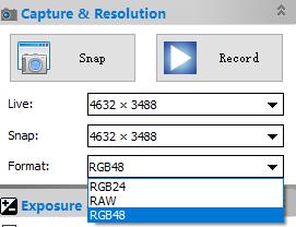
RGB24 represents RGB888, and you can only get 8-bit images per channel. If you select RAW, 12-bit (or 14-bit) raw data will be transferred to 16-bit raw data and saved in DNG file format. If you select RGB48, 36-bit RGB data (12-bit per channel, or 42-bit RGB data with 14-bit per channel) will be transferred to 48-bit RGB data and saved in TIFF file format.
Dragging images from disk to ToupView is a convenient way to open images in ToupView. However, if ToupView was opened during the installation process, users will fail when performing the drag operation. Restarting the software will solve this problem.
If the menu disappears, you can only uninstall the software and reinstall the software.
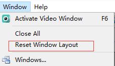
If the toolbar disappears and the menu is still valid, you can use the "Reset Window Layout" button in the "Window" menu. A restart is required for recovery.
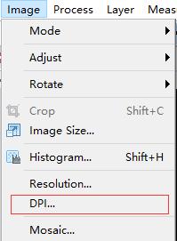
For the latest software, please use the DPI menu to change the DPI of captured images.
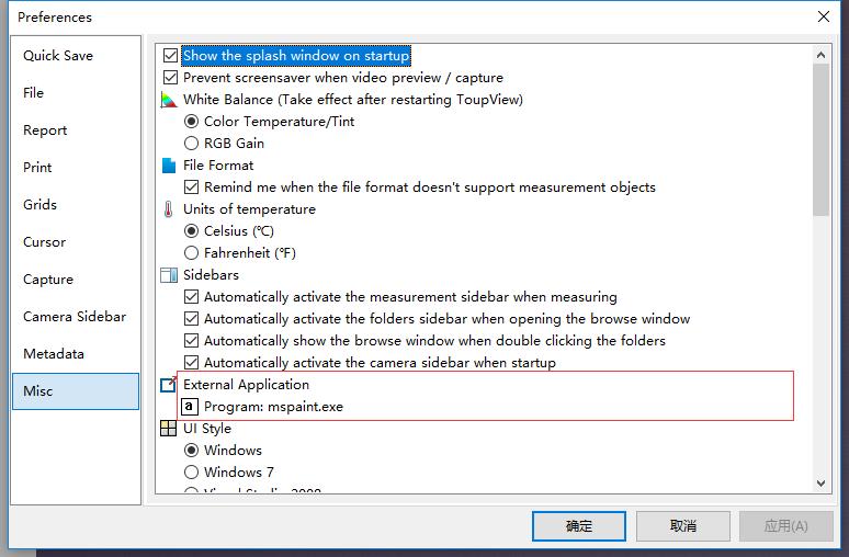
External processes will allow third-party software to directly open already opened images or preprocessed images. Some standard programs have this interface, such as Photoshop or mspaint.
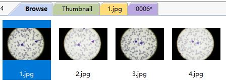
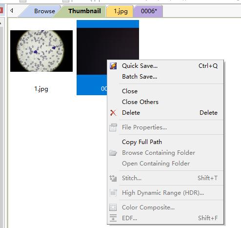
The folder is a browser for browsing all image files on disk. It is also an important platform for users to easily perform operations such as stitching, HDR, color composition, etc. However, you cannot find temporary files in the folder that are only captured from the software and not yet saved to disk.
After calibration, you must select the magnification in the toolbar, and you will see measurement objects in specified units rather than pixels.

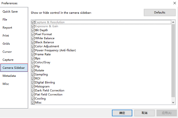
Please find it according to the following UI.

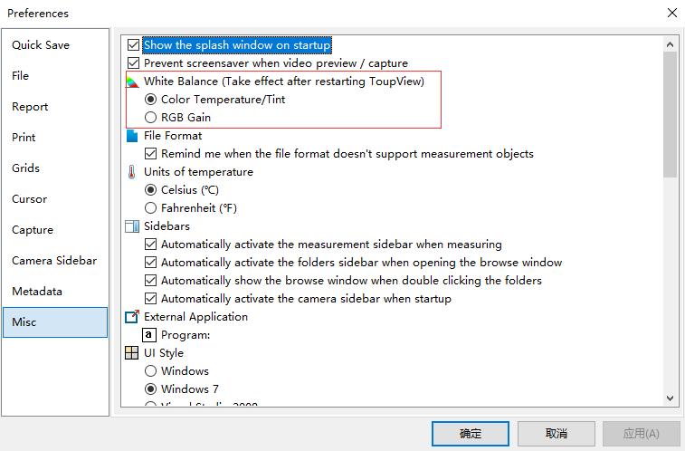
Yes, please select the white balance mode in the following UI, and a restart is required for the new setting to take effect.
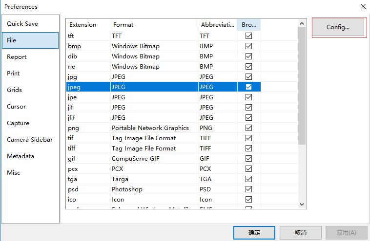
For BMP or other uncompressed images, image quality cannot be changed. For compressed image formats, image quality can be adjusted in the following UI in preferences settings by clicking the "Configure..." button.
For Windows software (ToupView), H.264, H.265, WMV, and AVI formats are supported.
- H.264 is supported on Windows 7 or higher. Each frame in the video file contains a timestamp, and the playback time of the recorded file is the same as reality.
- H.265 is supported on Windows 10 or higher. Each frame in the video file contains a timestamp, and the playback time of the recorded file is the same as reality. Using the same bit rate setting, better quality can be achieved than H.264 format.
- WMV is supported on all Windows platforms. Each frame in the video file contains a timestamp, and the playback time of the recorded file is the same as reality. All resolutions of all cameras can use this format. For horizontal resolutions larger than 4096, it is recommended to use third-party players such as VLC Media Player instead of the default Windows Media Player.
- AVI is outdated because it does not contain timestamps for frames. It only supports average frame rate settings and can only play frames at the specified frame rate. The duration of the entire video file will be set as accurately as possible. If MJPEG encoder format is specified, if the AVI file cannot be played by Windows Media Player (this happens on some computers when the video height is not a multiple of 4), please try using third-party software.
For Mac and Linux software, H.264 is used. The functionality is the same as that used on Windows software.
Please select the target language in preferences settings. The software needs to be restarted for it to take effect.

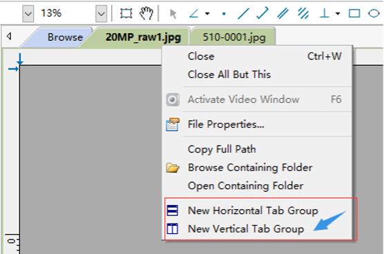
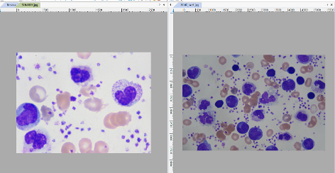
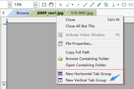
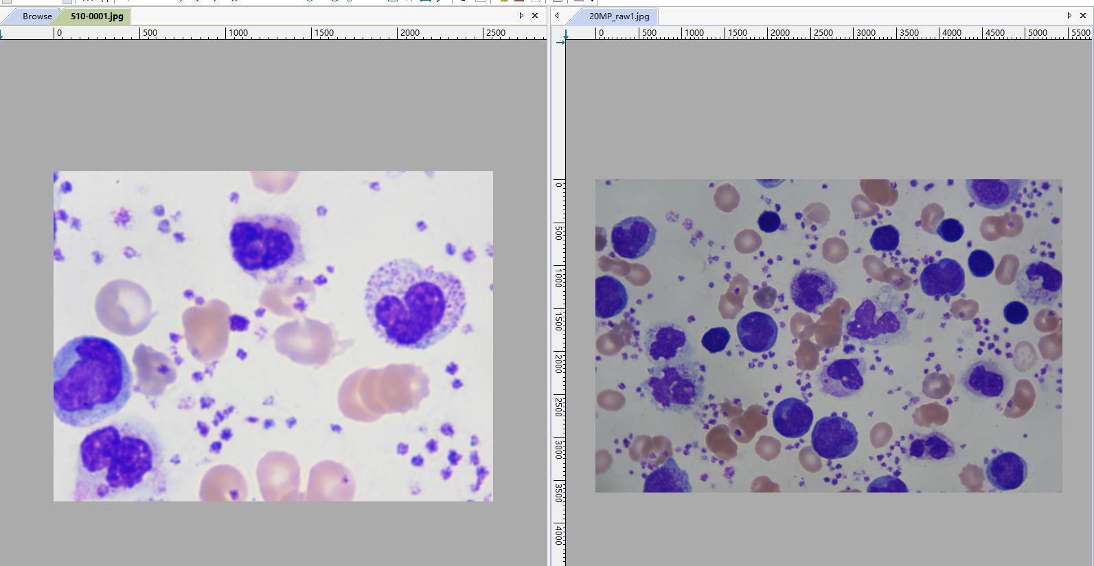
Please right-click on the video or image tab, then select "New Vertical Tab Group" or "New Horizontal Tab Group" to display videos or images simultaneously. Please see the following images for reference.
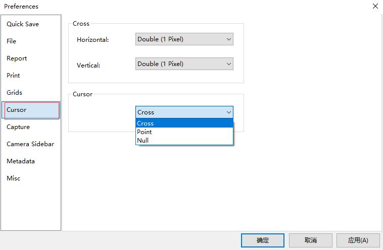
Yes. Please select the cursor type for the mouse in the "Preferences" settings, and then the mouse cursor will be replaced by your specified cursor, including crosshairs.
For fluorescence applications, exposure times are long and frame rates are very slow. This takes a long time, making it difficult for users to find focus. Sometimes this is unacceptable because some types of fluorescence fade very quickly. There are some methods to help solve this problem:
Reduce exposure time to increase frame rate. At the same time, adjust gain settings to increase brightness.
If the above method is considered to have too much noise or is still too dark to see objects, digital binning in additive mode will help increase brightness at the cost of resolution. 2×2 will increase brightness to 4 times the original brightness, and 4×4 digital binning will increase brightness to 16 times.
After finding focus, when users want full-resolution snapshots with specific gain settings, users can estimate exposure time based on current exposure time, gain, and digital binning settings.
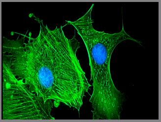
Alternatively, use the color composition function to color darker fluorescence images to obtain more recognizable fluorescence images.
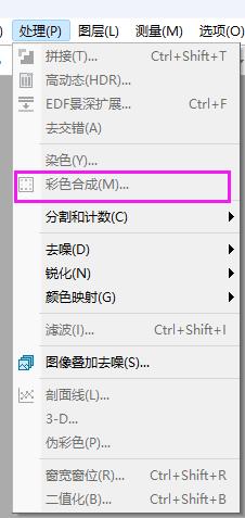
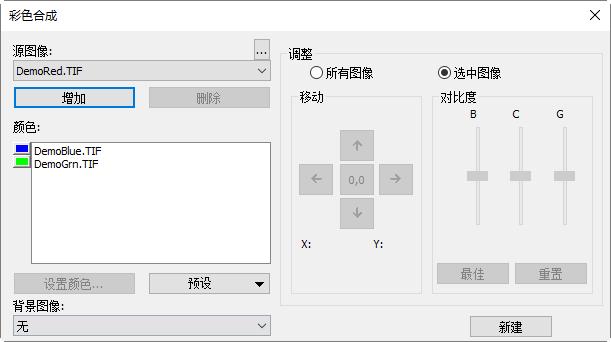
Color composition can use black and white source images to create and configure color composite images. The color composition dialog can be opened through the color composition menu item under the Process menu.
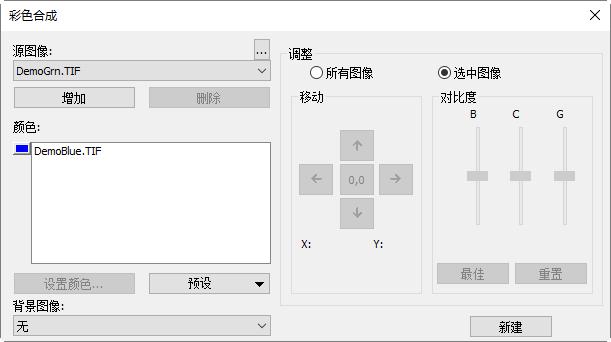
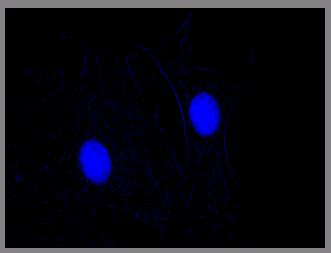
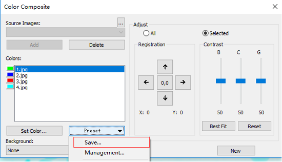
Multiple grayscale images can be combined into color composite images. Any grayscale images of the same size can be mixed in color composite images. Each input channel has independent LUT adjusters and alignment offsets so that it can align with the rest of the image. Independent channels can also be composed from a single image. Each channel will be listed separately, as shown in the figure below:
Flat field correction is used to correct uneven backgrounds caused by microscopes or illumination. Please first remove the sample and capture uneven background images. Then place the sample on the microscope and enable flat field correction. Please make sure to remove the sample when taking background images.
When conditions change, including optical systems, illumination, exposure time, or gain, FFC must be performed again under new conditions.
- First remove the sample to obtain uneven background.
- Set the number of background images. These uneven background images will be averaged and used as reference for FFC.
- Click the "Enable" button when the "Enable" button is grayed out.
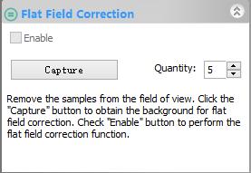
- Put the sample back in place.
Please check the following results for your reference.
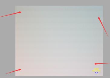
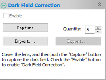
Dark field correction is used to eliminate noise or defective pixels caused by high temperature, readout channels, or long exposure. Dark frames are frames captured without illumination, including noise or defective pixels. Subtracting dark frames from captured frames will preserve useful information and eliminate noise or defective pixels.
Please note that when conditions change, including temperature, exposure time, and gain settings, DFC must be performed again.
- Please cover the camera with a cap to reduce illumination.
- Set the number of dark frames. These dark frames will be averaged and used as reference for DFC.
- Click the "Capture" button to obtain dark frames.
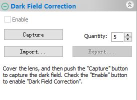
- Check the "Enable" button to enable the DFC function.
Quick recording is a method that allows users to record videos using preset options, including codec methods, video recording names, etc. When quick recording is enabled, users do not have to enter recording-related options every time.
- Please find the submenu in the "Preferences..." menu.

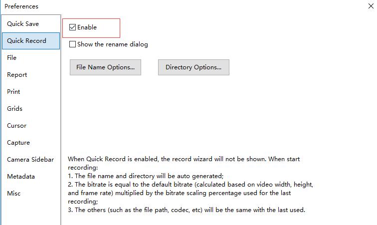
- Find the "Quick Recording" item in preferences settings, then check the "Enable" checkbox as shown below.
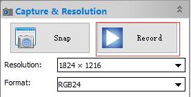
- Click "Record" to start quick recording.
The real-time stitching function allows real-time stitching in video mode. Users can get a rough understanding of the stitching area, and when frames update in video mode, the stitching results can be updated immediately. Automatic alignment and blending are applied during operation to achieve optimal performance.
- Click the camera name in the camera list to get video.
- Click the stitching button in the toolbar to open the real-time stitching window.

- The stitching window will display as follows. The grid area is the background.
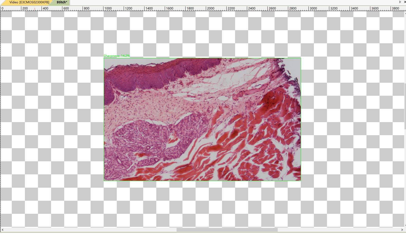
- Move the slide, and you will see stitching results during operation.
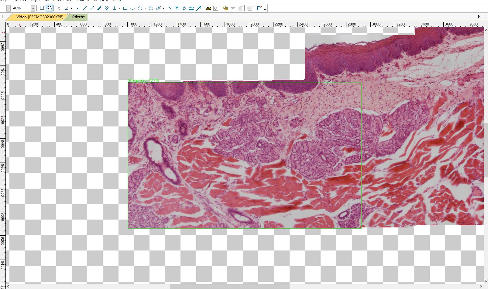
- The area marked with a green rectangle shows live video, and another area is the stitching result. Please note the rectangle. When the rectangle is green, the stitching function works as expected and users can move the slide. If the rectangle color is red or yellow, users should stop moving the slide. If the color is still red or yellow, users should move the slide slightly back to the area where the rectangle becomes green. After the rectangle is green, users can continue operating.
- Click the stitching button again to stop the real-time stitching function. The stitching result will be cropped from the background, and the result image will be automatically generated.
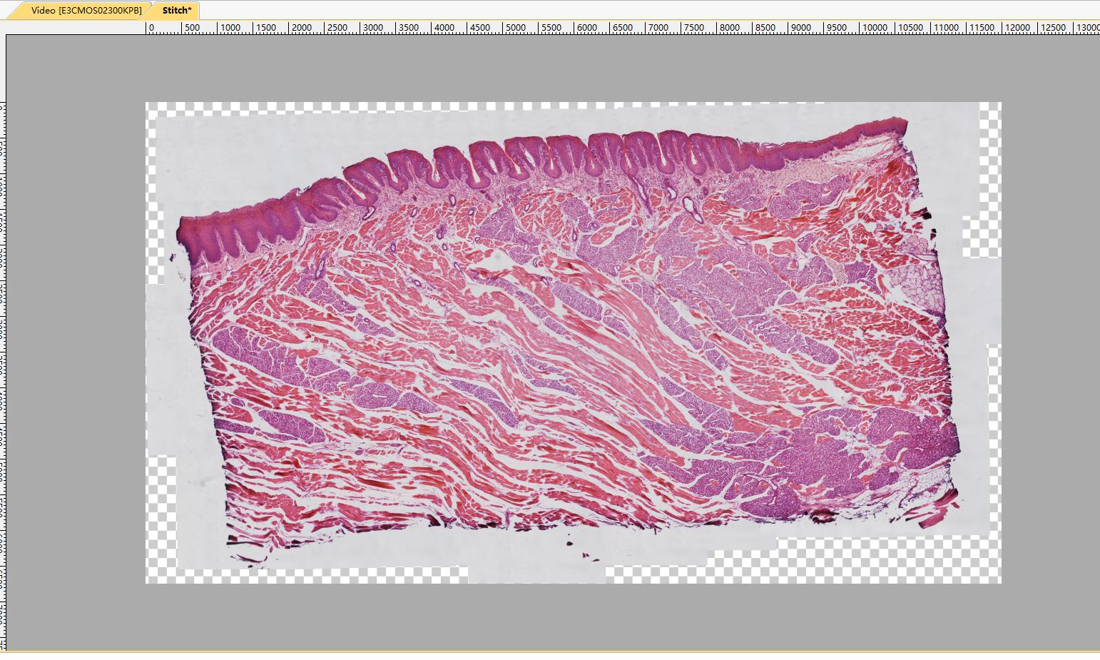
- The stitching result image can be saved or edited.
Notes:
- Cameras with global shutter sensors are preferred for optimal performance. Image distortion captured with rolling shutters may cause failure or unsatisfactory results.
- It is strongly recommended to turn off the auto-exposure function during stitching operations to ensure consistent brightness.
- High-speed cameras are preferred to achieve the best experience. If illumination is strong enough, shorten exposure time to ensure high frame rates.
- Users should move slides at appropriate speeds and ensure the camera is in focus. When the rectangle in the stitching window turns red or yellow, users should stop or move back a bit until the rectangle becomes green. Red or yellow rectangles during stitching operations indicate stitching or alignment failure or warning. The reason may be due to slides moving too fast, in which case the computer is not fast enough to complete calculations, or the content details are not clear enough for alignment.
- Please stop the stitching window before closing the stitching window.
Please watch the video demonstration of the real-time stitching function at the following link:
www.mediafire.com/file/fdhwe68e4cabdq7/live+stitching+demo_ToupView_2018-08-14.mp4.
The real-time EDF function in ToupView software allows real-time extended depth of field in video mode. When the depth of field is shallow and the specimen has a certain thickness, EDF helps build images that focus as accurately as possible on all parts. Real-time EDF means that the real-time results of the EDF function can be updated immediately during the EDF process, and users can adjust the process according to the real-time results. Automatic alignment is applied during operation to achieve optimal performance in case of slight FOV (field of view) offset.
- Click the camera name in the camera list to get video.
- Click the EDF button in the toolbar to open the real-time EDF window.

- The real-time EDF window will display as follows. The left window is the real-time preview window of the camera, and the right window is the real-time EDF result.
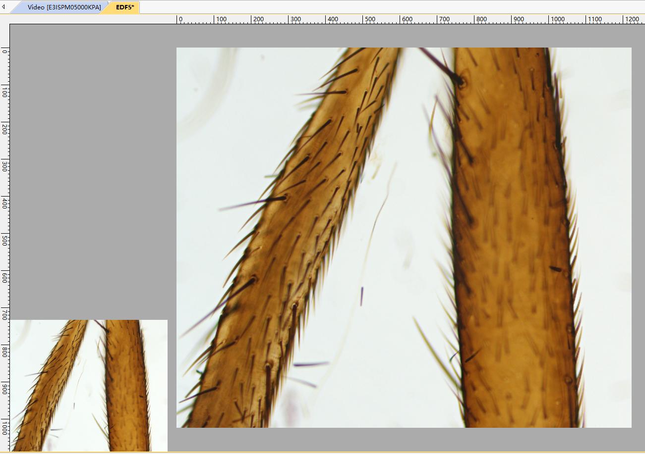
- Adjust the position of the specimen in Z order. The real-time preview of the specimen will be displayed in the left video window. The EDF result will be updated in real-time in the right window.
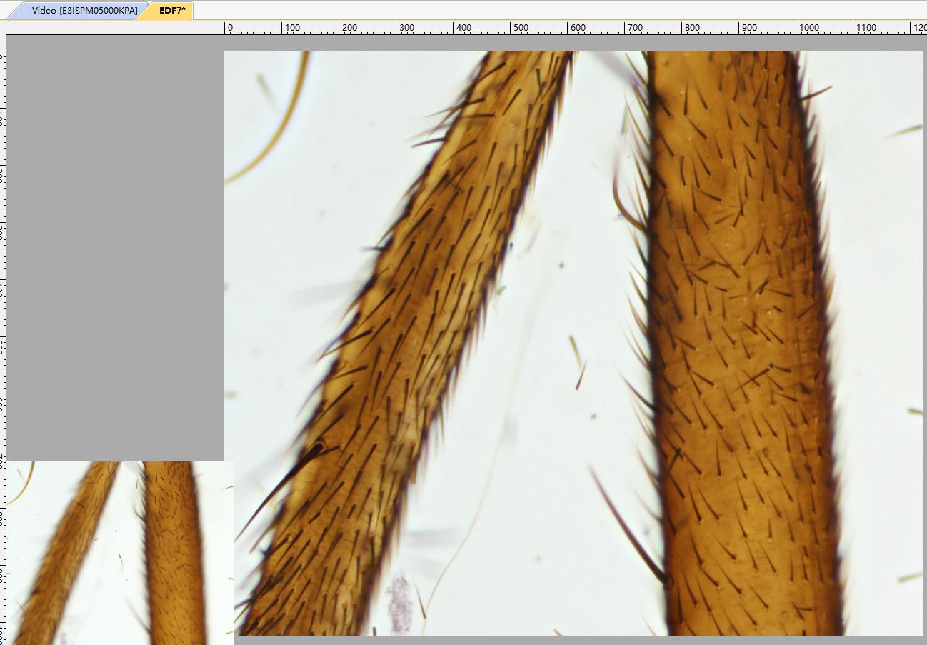
- Click the EDF button again to stop the real-time EDF function.
Notes:
- Settings related to real-time EDF are integrated in the "Preferences" settings, as shown in the following snapshot.
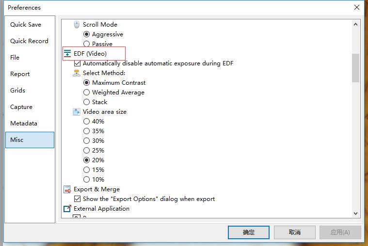
- Real-time EDF provides three methods, including "Maximum Contrast" method, "Weighted Average" method, and "Stacking" method. The "Maximum Contrast" method is the default method.
- It is best to disable auto-exposure during this process.
- The real-time preview window size can be changed from 10% to 40%, and the EDF result window size can be easily adjusted by the mouse middle button or zoom settings in the toolbar.
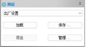
After setting camera parameter configurations in the camera sidebar, you can save the set camera parameter configurations in the preset function bar. You can load saved camera parameter configurations through the load function.
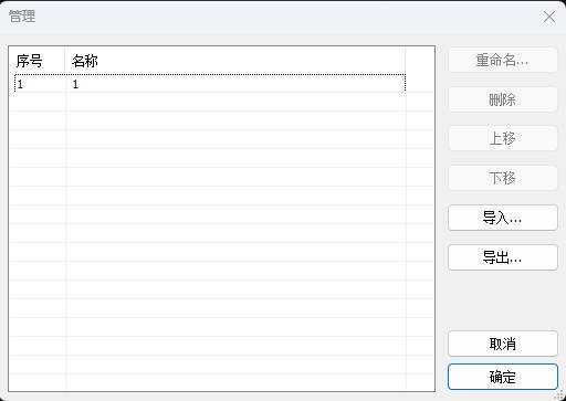
You can modify and import/export saved camera parameter configurations through the management function.
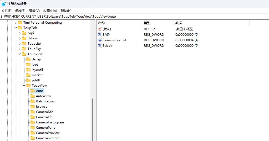
Stored in the registry (ToupView software's default storage method). Parameters are automatically loaded when the camera is opened, and parameters are automatically saved when the camera is stopped. In the registry at: Computer\HKEY_CURRENT_USER\Software\ToupTek\ToupView\ToupView directory.
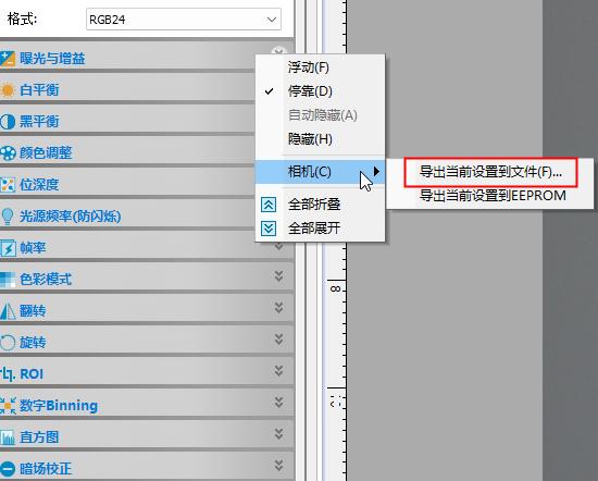
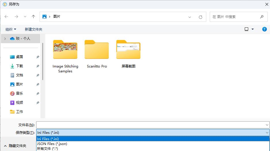
Stored in .ini or .json files. Right-click in the blank area of the camera sidebar to call up the sidebar settings, where the current settings can be exported to files in the camera options.
Stored in the camera hardware's EEPROM (camera has EEPROM device). Similarly, right-click in the blank area of the camera sidebar to call up the sidebar settings, where settings can be exported to EEPROM in the camera options.

ROI is divided into hardware ROI and software ROI. Hardware ROI can improve camera frame rate.
Hardware ROI: Sets the sensor's working parameters, reducing data read from the sensor (thus improving frame rate).
Software ROI: Does not change the sensor's working parameters. The amount of data read from the sensor remains unchanged. The upper-level software crops the original image to the target ROI rectangle size.
From the static and dynamic distribution of bad pixels, they can be divided into static bad pixels and dynamic bad pixels. From pixel brightness, they can be divided into bright spots and dark spots.
Static Defective Pixel (SDP) is caused by chip defects in image sensor technology. The solution is based on a predetermined static bad pixel table, comparing whether the current coordinates are consistent with certain coordinates in the static bad pixel table. If the coordinates are consistent, it is determined as a bad pixel, then the correction result is calculated and corrected.
Dynamic Defective Pixel (DDP) is related to sensor temperature and gain. When sensor temperature increases or gain value increases, dynamic bad pixels will increase.
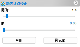
The dynamic bad pixel correction function in the software sidebar uses algorithms to determine whether a point is a bad pixel. If it is a bad pixel, correction is performed. The correction can set thresholds and values.
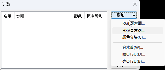
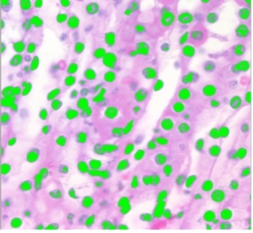
Select Process > Segmentation & Counting menu to implement segmentation and counting measurement functions for images of interest. The App's segmentation and counting menu is designed quite specially, detailed as follows:
The App's segmentation and counting provides 6 image segmentation methods for users to call according to image characteristics. These 6 segmentation methods are: Watershed, Dark OTSU, Bright OTSU, RGB Histogram, HSV Histogram, Color Blocking, etc. Users can select any one of these 6 segmentation methods for segmentation, but after selecting one segmentation method, other segmentation methods will be disabled.
After segmentation is completed, there may be adhesion situations of counting objects, so manual segmentation of adhesive objects is necessary.
After confirming that the expected results are achieved, you can select the counting results menu to implement result statistics and analysis for segmented images.
The toolbar magnification setting does not apply to images; it only applies to video. You can check and change the magnification by clicking the resolution button in the image menu (Figure 1).
Then the resolution setting dialog will pop up (Figure 2), where you can change calibration information. If the resolution value is 0, it means the image has no calibration information.
You can specify the magnification in the magnification dropdown. If the resolution value is not 0 and you still see objects in pixel units, please check the selected unit setting in the toolbar.
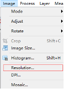
Figure 1
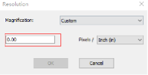
Figure 2
Dark field correction is usually used to eliminate background noise or fixed pattern noise. Dark frames must be captured without illumination.
For long exposure applications, dark current noise is obvious, and users can remove dark current noise through the dark field correction process. It can also help remove defective pixels when long exposure is required.
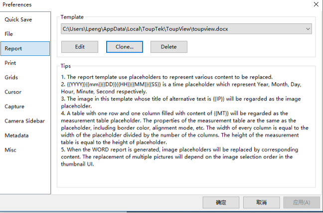
The Word report function is designed to export images and other useful information to Word files according to template format.
The report template is a Word format file that contains different types of placeholders, which uses placeholders to represent content to be replaced. Currently supports 3 different types of placeholders: time placeholders, image placeholders, and measurement table placeholders.
{{YYYY}}{{mm}}{{DD}}{{HH}}{{MM}}{{SS}} are time placeholders, representing year, month, day, hour, minute, second respectively.
Images with title item {{IP}} in the alternative text property of this template will be regarded as image placeholders.
Tables with one row and one column filled with {{MT}} content will be regarded as measurement table placeholders. The properties of the measurement table are the same as the placeholder, such as border color, alignment mode, etc. The width of each column equals the placeholder width divided by the number of columns. The height of the measurement table equals the placeholder height.
When generating WORD reports, different placeholders in the template will be replaced by corresponding content in the software. Users can define their own templates and rearrange placeholders in their own templates according to their requirements. The 'Clone' button is used to copy existing templates. Select the cloned template in the template list, then click the 'Edit' button to modify the template. When users want to insert more placeholders, please ensure that the newly inserted 'placeholders' are recognized as placeholders by the software. For details, please refer to the placeholder description above.
After the template is completed, users can select content in the software to replace placeholders in the template.
1) Time placeholders
Users do not need to set content for time placeholders as they will be automatically set by the software system.
2) Image placeholders
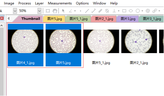
When users want to export images to templates, they must first open images through the software. Then you will see the opened images in the thumbnail browser.

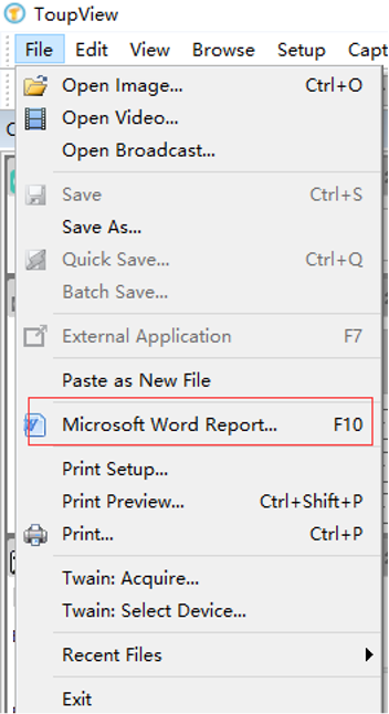
Select the images to be exported in the thumbnail browser, then click the 'Microsoft Word Report' button to complete. The replacement of multiple images in the template will depend on the image selection order in the thumbnail UI.
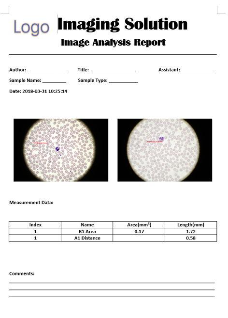
3) Measurement table placeholders
Measurement table placeholders will be replaced with measurement information of exported images. Users can manage exported measurement information in the following 'Measurement' dialog before export.
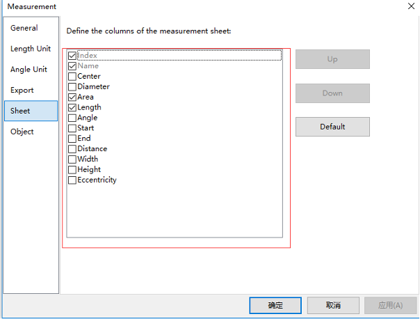
If the menu disappears, you can only uninstall the software and reinstall the software.
If the toolbar disappears and the menu is still working, you can use the 'Reset Window Layout' button in the 'Window' menu. A restart is required for recovery.
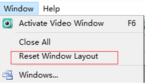
Figure 1
Dragging images from disk to ToupView is a convenient way to open images in ToupView. However, if ToupView is opened during the installation process, users will fail when performing drag operations. Restarting the software will solve this problem.
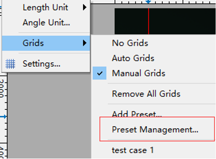
The new version software can save grids to preset items for later use. Please follow these steps:
1. Right-click the mouse in that area, as shown below
2. Select manual grid in the pop-up menu.
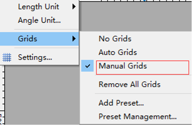
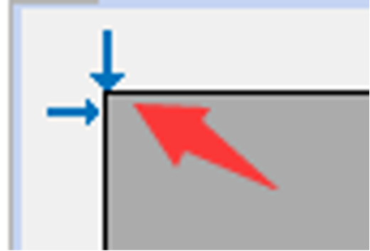
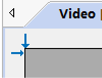
3. Drag the blue arrows to the video window (vertical or horizontal) to set the position of the grid
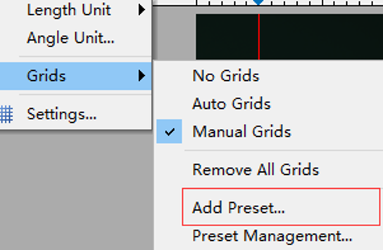
4. Click 'Add Preset' and enter a name to add the current grid to the preset list.

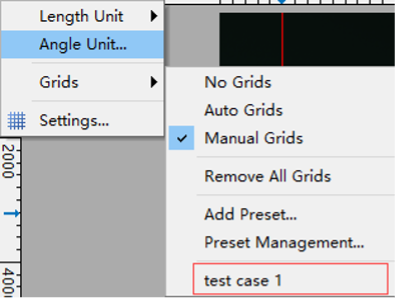
5. Users can select preset grids in the pop-up menu for later use.
6. To manage saved preset options, export or import grids, select 'Preset Management' and operate in the pop-up dialog.
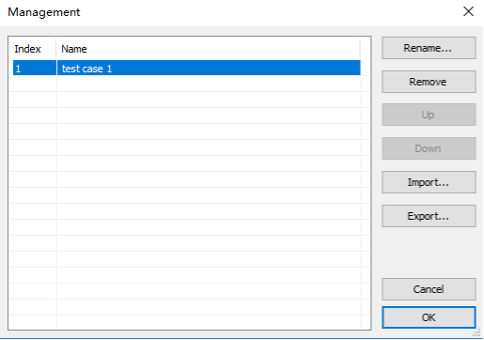
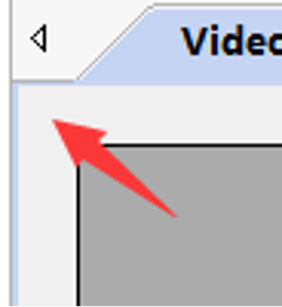
After selecting manual grid in the menu View->Grid, you can see 2 small blue arrows in the upper left corner of the video or image window. Dragging the arrows to the position you want will generate a line. Repeating this operation will generate more lines. The operation is the same for vertical and horizontal directions.
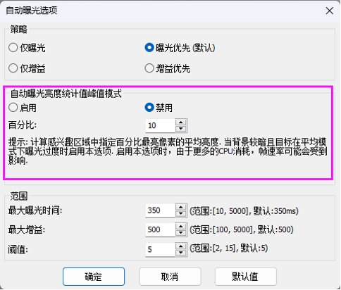
Auto exposure peak mode can be enabled in the camera sidebar exposure and gain function options.
Enabling this function calculates the average brightness of the brightest pixels of a specified percentage in the selected exposure ROI area. Enable this option when the background is dark and the target is overexposed in average mode.
When this function is enabled, there will be more CPU consumption and frame rate may be affected.
In older software versions, we used the DPI part of image files to save calibration information. The disadvantage of this method is that images with calibration information become very small when opened through Excel.
The new software uses a new method that does not affect DPI, solving the above problem. However, BMP format does not support this new method. When users want to save images with calibration or measurement information, please select other formats.
SDK Development
ToupView software can support recognition of multiple cameras. However, users cannot open multiple cameras simultaneously through ToupView. Users must first close the opened camera, then open another camera.
However, opening multiple cameras can be supported by SDK. A simple demonstration is provided to open multiple cameras for reference.
Yes, please check the beginning of the toupcam.h file, and you will find the following information.
/* Version: 27.12147.2018.0616 */
Please refer to the following specifications
Platforms and architectures:
1) Win32:
- x86: XP SP3 or higher; CPU supports SSE2 instruction set or above
- x64: Win7 or higher
2) WinRT: x86 and x64; Win10 or higher
3) macOS: x86 and x64 bundle; macOS 10.10 or higher
4) Linux: kernel 2.6.27 or higher
- x86: CPU supports SSE3 instruction set or above; GLIBC 2.8 or above
- x64: GLIBC 2.14 or above
- armel: GLIBC 2.17 or above; built by toolchain arm-linux-gnueabi (version 4.9.2)
- armhf: GLIBC 2.17 or above; built by toolchain arm-linux-gnueabihf (version 4.9.2)
- arm64: GLIBC 2.17 or above; built by toolchain Aarch64-Linux-GNU (version 4.9.2)
ToupCam SDK does not save and load parameters as preset settings. Users can implement this functionality in their own code. Users typically save preset settings to files or registry.
The reason is that different applications have very different requirements for parameter saving. Some parameters need to be saved while others do not. Some applications need to save parameters in files while others need to save in registry. Some applications even require saving parameters unrelated to cameras.
If users do not know how to write and read registry, we can provide demonstrations.
1. Use FLAG_PRECISE_FRAMERATE to determine if camera supports precise frame rate setting
2. If camera does not support precise frame rate setting, call put_Speed to set frame rate, with maximum value obtained by MaxSpeed
3. If camera supports precise frame rate setting, set through OPTION_PRECISE_FRAMERATE, with maximum value obtained by OPTION_MAX_PRECISE_FRAMERATE
Our main SDK version only supports obtaining image memory data and does not provide functionality to save images to files. Depending on the framework used, there are different methods to save images. For example, demomfc demonstrates how to call WIC components to save images, demowinformcs demonstrates how to call C# functions to save images, demoqt demonstrates how to call Qt functions to save images. Additionally, the extra file directory in SDK provides an additional library imagelib specifically for saving images.
If customers know how to save image data to computer, we recommend they use methods they are familiar with. If not familiar, they can also adopt methods demonstrated in our SDK demos or use the additional library imagelib.
Create a toupcam.log file in the toupcam.dll directory, run the program again, and logs will be written to the toupcam.log file.
ToupCam SDK returns error codes in two ways: first, through direct return values of API functions; second, through EVENT events to notify the host computer.
Method one is the primary solution, method two is a supplement to method one.
- Through direct return values HRESULT of API functions
Except for a few functions without return values in ToupCam SDK, other API return values are all HRESULT, using Windows standard error codes. The following are error codes used by ToupCam SDK:
|
Error Code |
Macro Definition |
Meaning |
|
0x00000000 |
S_OK |
Operation completed successfully |
|
0x00000001 |
S_FALSE |
Operation failed |
|
0x8000ffff |
E_UNEXPECTED |
Catastrophic failure |
|
0x80004001 |
E_NOTIMPL |
Not implemented |
|
0x80004002 |
E_NOINTERFACE |
Interface not supported |
|
0x80070005 |
E_ACCESSDENIED |
Access denied |
|
0x8007000e |
E_OUTOFMEMORY |
Insufficient memory resources to complete this operation |
|
0x80070057 |
E_INVALIDARG |
Invalid parameter |
|
0x80004003 |
E_POINTER |
Invalid pointer |
|
0x80004005 |
E_FAIL |
Unspecified error |
|
0x8001010e |
E_WRONG_THREAD |
Application called an interface marshaled for another thread |
|
0x8007001f |
E_GEN_FAILURE |
Device attached to the system is not functioning |
|
0x800700aa |
E_BUSY |
Requested resource is in use |
|
0x8000000a |
E_PENDING |
Data necessary to complete this operation is not yet available |
|
0x8001011f |
E_TIMEOUT |
Operation returned because timeout period expired |
|
Others |
|
Unknown error |
Based on the API function name and its return value, you can determine what problem occurred. For example, if Toupcam_put_Size returns 0x80070057 error, it indicates parameter error when setting resolution.
- Through EVENT events
Mainly the following four events (passed through messages in Toupcam_StartPullModeWithWndMsg or callback functions in Toupcam_StartPullModeWithCallback or callback functions in Toupcam_StartPushMode V3, V4):
|
Error Code |
Macro Definition |
Meaning |
|
0x0080 |
TOUPCAM_EVENT_ERROR |
Unknown error |
|
0x0081 |
TOUPCAM_EVENT_DISCONNECTED |
Camera disconnected |
|
0x0082 |
TOUPCAM_EVENT_NOFRAMETIMEOUT |
No data frame received |
|
0x0085 |
TOUPCAM_EVENT_NOPACKETTIMEOUT |
No data packet received |
1. Use FLAG_PRECISE_FRAMERATE to determine if camera supports precise frame rate setting
2. If camera does not support precise frame rate setting, call put_Speed to set frame rate, with maximum value obtained by MaxSpeed
3. If camera supports precise frame rate setting, set through OPTION_PRECISE_FRAMERATE, with maximum value obtained by OPTION_MAX_PRECISE_FRAMERATE
Enumerate cameras
Function: Toupcam_EnumV2
Example: ToupcamDeviceV2 devices[TOUPCAM_MAX];
int cnt = Toupcam_EnumV2(devices);
Description: cnt represents the number of detected camera devices
Open camera
Function: Toupcam_Open
Example: HToupcam hcam = Toupcam_Open(devices[0]->id);
Description: devices[0]->id represents the ID number of the first enumerated camera, hcam represents the handle
Run camera
Function: Toupcam_StartPullModeWithWndMsg or Toupcam_StartPullModeWithCallback
I do not know if vb6.0 supports messaging mechanism, if not supported, use Toupcam_StartPullModeWithCallback
Example 1: Toupcam_StartPullModeWithWndMsg(hcam, hwnd, msg);
Close camera
Function: Toupcam_Close
Example: Toupcam_Close(hcam);
See details:
Flat field correction (FFC) is used to correct uneven background caused by optical system or illumination. When conditions change, including optical system, illumination, exposure time or gain, FFC must be performed again under new conditions. SDK can support flat field correction (FFC).

The above options are used to enable/disable FFC function, set average number and get current status of FFC.
1. Remove samples or objects from field of view to obtain background.
2. Set average number by setting TOUPCAM_OPTION_FFC option.
3. Call the following function to obtain background image.

4. TOUPCAM_EVENT_FFC event will occur to indicate different internal states. Listen to TOUPCAM_EVENT_FFC event and check status using TOUPCAM_OPTION_FFC option until status is 'Started'.
5. When status is 'Started', enable FFC function by setting TOUPCAM_OPTION_FFC option to 1.
Yes, please check the beginning of the toupcam.h file, and you will find the following information.
/* Version: 27.12147.2018.0616 */
Dark field correction is used to eliminate noise or defective pixels caused by temperature or long exposure. SDK supports dark field correction.

The above options are used to enable/disable DFC function, set average quantity and get current status of DFC.
1. Cover the camera with a dark cover to obtain a dark field of view.
2. Set average number by setting TOUPCAM_OPTION_DFC option.
3. Call the following function to obtain background image.

4. TOUPCAM_EVENT_DFC event will occur to indicate different internal states. Listen to TOUPCAM_EVENT_DFC event and check status using TOUPCAM_OPTION_DFC option until status is 'Started'.
Enable DFC function by setting TOUPCAM_OPTION_DFC option to 1
Optical Lenses
The following parameters need to be provided: ① working distance; ② target range for shooting; ③ camera model and parameters to be matched. Any other requirements can also be specified.
FMA and AMA are typically calculated and selected for magnification according to 18/20 mm intermediate image circle size.
Optical interfaces for major four brands are typically calculated for magnification according to 24 mm intermediate image circle size.
For example, if camera sensor is 2/3 inch (diagonal size 11 mm), you can choose 0.5X optical interface because 24×0.5=12 mm is already larger than the camera sensor diagonal size, so no vignetting will occur.

