DIC100 Series Differential Interference Contrast Microscopy System

For Purchase / Trial / OEM / ODM, Please Contact Us

ToupTek

Introduction

DIC100 Series Differential Interference Contrast Microscopy System

The DIC (Differential Interference Contrast) microscope system utilizes the principle of dual-beam polarized interference. The process is as follows:

1. The linearly polarized light from the polarizer passes through a Nomarski prism (which exhibits birefringence) and is split into two perpendicularly vibrating polarized beams with a certain phase difference;

2. After illuminating the sample, the slight surface unevenness or varying refractive indices in the field introduce an optical path difference between the two incoherent beams. These beams are then recombined by the Nomarski prism after reflecting off the sample;

3. The recombined light passes through the analyzer, aligning their vibration directions and creating interference;

4. The sample details become enhanced in contrast due to interference and amplitude variations, rendering the image with a three-dimensional, relief-like effect.

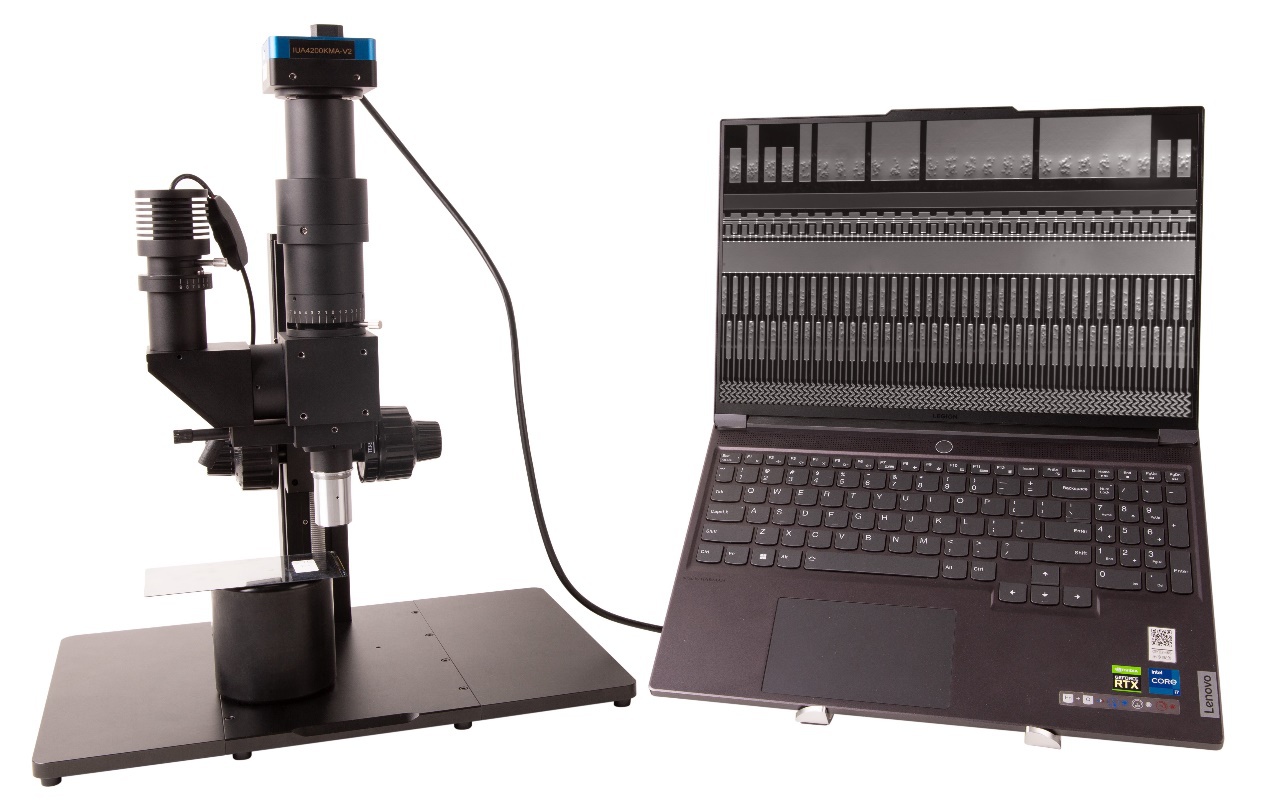
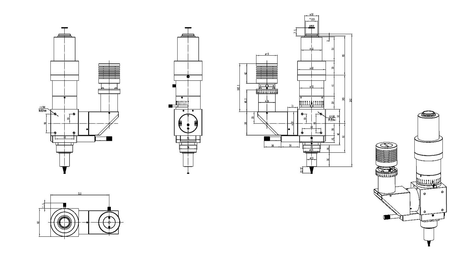
The Nomarski prism can be adjusted horizontally, functioning similarly to a phase compensator, which changes the brightness and interference colors between the object and background in the field of view to achieve the ideal observation effect. The left image shows the DIC100 series Differential Interference Contrast microscope system.

Key Features of the DIC100 Series Differential Interference Contrast Microscope System:

  • Standard working distance series / long working distance series objectives (optional);
  • Imaging optical path: 1X (tube lens focal length 180mm), with the option to customize various reduction lenses;
  • Image plane size of the optical path: 25mm;
  • Spectral range of the optical path: Visible light;
  • Camera interface options: C/M42/M52, etc. (optional);
  • Illumination options: Critical illumination / Köhler illumination (optional);
  • Light source: 10W white/blue LED illumination (optional);

System Parameters

Standard Working Distance Objective Parameters (60mm parfocal, 200mm tube lens focal length)

Order code

Magnification

NA

WD/mm

Focal length(mm)

Resolution(um)

OFOV(mm)

IFOV(mm)

Thread

DIC2.5XA

2.5X

0.075

6.2

80

4.46

10

25

M26*0.705

DIC5XA

5X

0.15

23.5

40

2.2

5

25

M26*0.705

DIC10XA

10X

0.30

22.8

20

1.1

2.5

25

M26*0.705

DIC20XA

20X

0.40

19.2

10

0.8

1.1

25

M26*0.705

DIC50XA

50X

0.55

11.0

4

0.6

0.44

25

M26*0.705

Long Working Distance Objective Parameters (60mm parfocal)

Order code

Magnification

NA

WD/mm

Focal length(mm)

Resolution(um)

OFOV(mm)

IFOV(mm)

Thread

DICL2.5XA

2X

0.055

33.7

100

6.1

12.5

25

M26*0.705

DICL5XA

5X

0.14

33.6

40

2.2

5

25

M26*0.705

DICL10XA

10X

0.28

33.4

20

1.2

2.5

25

M26*0.705

DICL20XA

20X

0.34

29.5

10

0.8

1.25

25

M26*0.705

DICL50XA

50X

0.5

18.9

4

0.7

0.5

25

M26*0.705

Application Areas

Conductive Particle Inspection for LCD/OLED and Similar Products

The number of conductive particles on LCD circuitry is key to its electrical performance. Too few particles can reduce conductivity and may cause display malfunctions; too many particles can result in material wastage, and agglomerated particles may cause significant errors in particle counting, leading to lower reported counts than the actual numbers, which affects the accuracy of the inspection results.

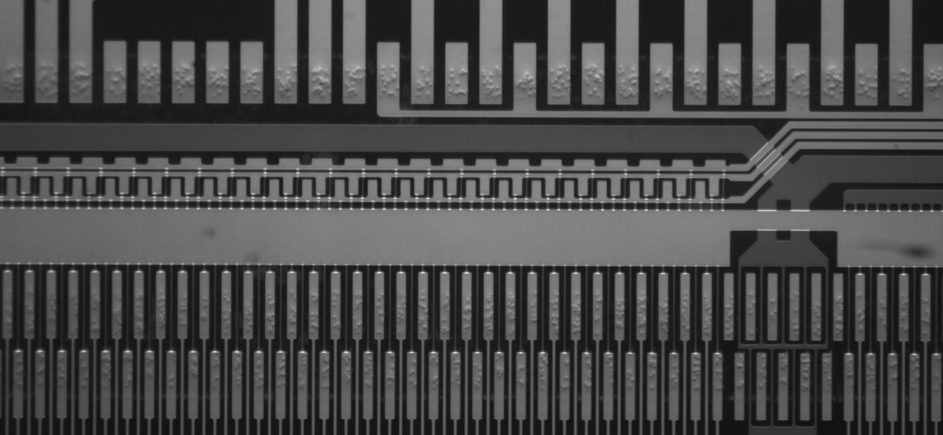
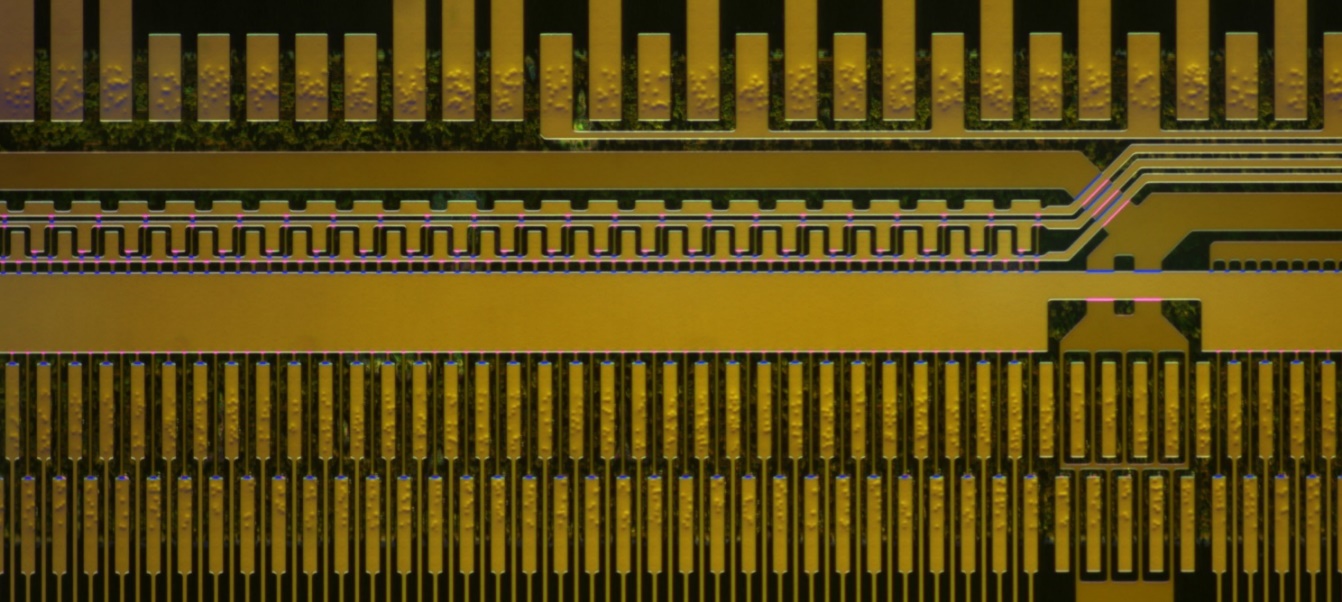
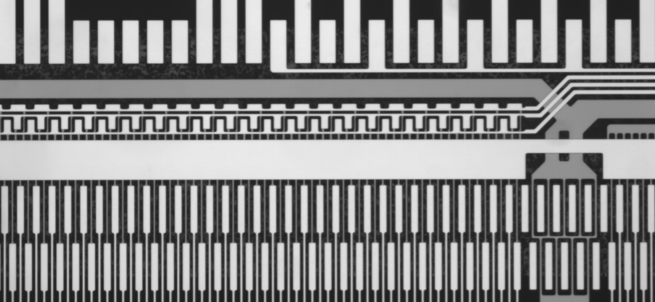
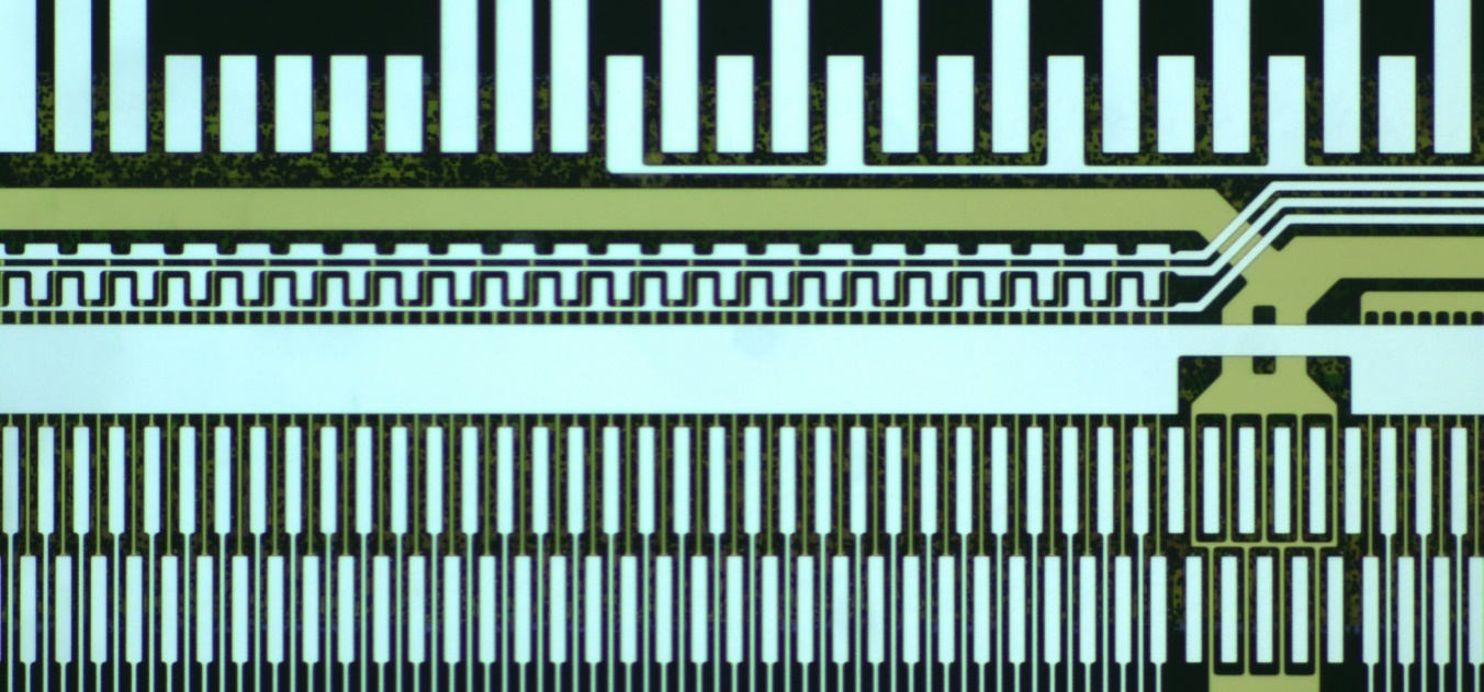
Figure 3 shows an image of conductive particles on an LCD captured with the DIC100 series microscope system; Figure 4 shows an image of the same area captured with a metallurgical microscope. In Figure 3, the conductive particles are clearly outlined, whereas in Figure 4, the metallurgical microscope fails to reveal them.

DIC100 series microscope system capturing LCD conductive particles (left) with blue LED illumination + monochrome camera; (right) with white LED illumination + color camera
LCD display captured with a metallurgical microscope (left) using blue LED illumination + monochrome camera; (right) using white LED illumination + color camera

The left image, taken with a conventional metallurgical microscope, barely shows or does not reveal the fine structures or defects on the LCD panel, whereas the DIC100 series microscope system easily captures these details. Additionally, the DIC100 system can observe micro-particles, pores, cracks, and uneven contours in the sample, making material analysis more reliable.

Microorganism Cell Detection

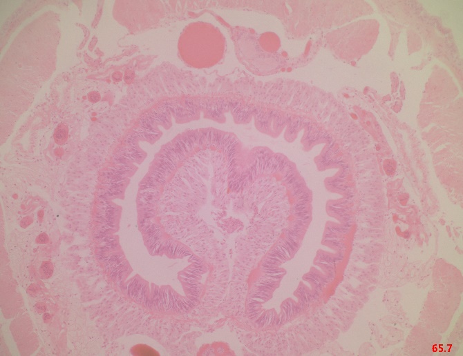
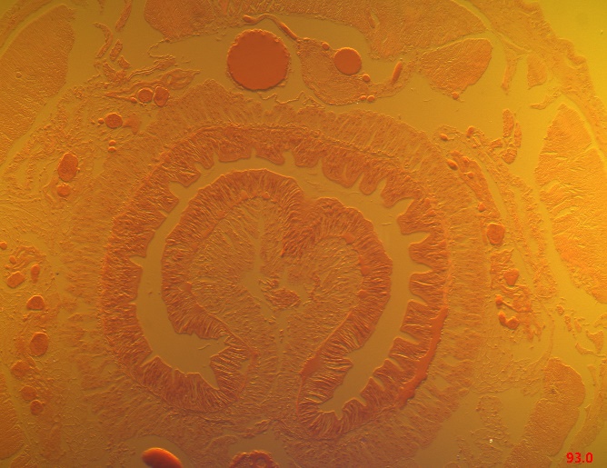
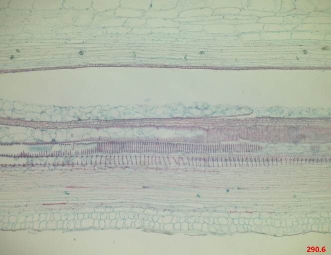
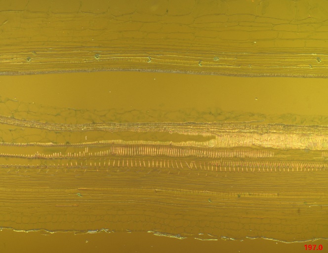
The DIC100 series microscope system is capable of non-destructive activity detection on live cells. By adjusting the optical staining, it can generate images with distinct interference colors; varying the focus yields clear images of different layers; and its high resolution clearly displays cellular contours and structures. Figures 6 and 7 show the comparative results.

DIC100 Series
DIC100 Series
Earthworm slice captured with a biological microscope (left) and with the DIC100 series microscope system (right)
DIC100 Series
DIC100 Series
Cucurbit Stem slice captured with a biological microscope (left) and with the DIC100 series microscope system (right)